
![]()
AGi32 Interface - Procedure
Finding commands
The menu bar contains pull-down menus that access commands and settings within AGi32. Icons that represent commands are in various locations on the interface and provide graphical accessibility to the AGi32 commands. The Model Toolkits may be docked left or right on the desktop or may float above the graphics window. They can also be disconnected to move to a secondary monitor. All docking commands are accessible from a right-click menu on the toolkit titlebar.
As the mouse moves over the toolbars, the cursor is in the form of an 11 o'clock arrow to assist in selecting a command. When the cursor rests on an icon for a second, a tool tip describing the icon's command will appear. As the mouse moves over the graphics window, the cursor changes to cross hairs to locate objects in the graphics window. Some commands prompt you to select an entity to modify. In this case, the cursor will change to a pickbox to aid in selecting the desired object.
- To select a command, left click on the icon or menu selection.
- To see the available command options, left click on the pull-down arrow to the right of the command icon. Select the desired menu option.
- You may cancel a command by using the Esc key on your keyboard.
- Conclude a command by clicking the right mouse button. When no command is active, clicking the right mouse button will reactivate the previously used command. Exceptions: Save, Save As, and Calculate are not repeated by right clicking.
- The mouse wheel will zoom into (roll forward) and out of (roll backward) the Model Mode graphics area. Hold down the wheel to Pan, press the shift key while holding down the wheel to interactively orbit an isometric view.
- The command line at the bottom of the screen will prompt you for the required information. The word "select" on the command line indicates you can graphically select the entity or vertex with the mouse. The word "enter" indicates you can type in the information from the keyboard. When entering information from the keyboard, press Enter to submit the information once you have completed typing.
- Within a command that requires specifying a boundary (like a room or calculation polygon), you can undo an erroneous line segment with Ctrl-Z or the Undo key on the AGi32 Common Toolbar.
When graphically specifying vertices or radius information with the mouse in AGi32, you may use absolute or relative coordinates.
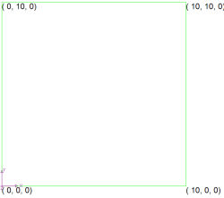
AGi32 uses a 3-dimensional Cartesian Coordinate system consisting of X, Y and Z axes. This system is called a WCS (world coordinate system). In a WCS displaying Plan View, X is defined as running left to right on the screen (East-West), Y is up and down (North -South) and the positive (+) Z-AXIS is perpendicular to the display and pointing towards you.
In Elevation Views, Z points up and down on the screen and X and/or Y may run left to right, depending on the elevation view taken.
Every entity in AGi32 is specified in terms of 3 coordinates. These coordinates remain constant to the WCS display and do not flip if an alternate view is taken. In other words, in an elevation View, one is always working with Z coordinates, not just X and Y.
Absolute coordinates
This input method allows you to enter the coordinates in relation to the Cartesian coordinate system with the origin at 0,0,0.
For example, to create a rectangular-flat room with three point input that is 10 x 10 feet in X and Y you would enter the following coordinates:
|
|
This input method allows you to enter coordinates relative to the current (or last) point entered.
For example, to create a rectangular-flat room with three point input that is 10 feet x 10 feet in X and Y you would enter the following relative coordinates:
|
|
Four options are available:
- Length@Angle – Actual point is located a specified distance and angle from the current point. Example: Current point = (0, 0, 0), relative coordinates =(100@45), actual point = (70.7, 70.7, 0)
- @X – Actual point in located a specified distance in the X direction from the current point. Example: Current point = (0, 0, 0), relative coordinates = (@100), actual point = (100, 0, 0)
- @X,Y - Actual point in located a specified distance in the X and Y directions from the current point. Example: Current point = (0, 0, 0), relative coordinates = (@100,50), actual point = (100, 50, 0)
- @X,Y,Z – Actual point in located a specified distance in the X, Y and Z directions from the current point. Example: Current point = (0, 0, 0), relative coordinates = (@100,50,25), actual point = (100, 50, 25)
Notes:
- In Plan and Isometric View, any of the input methods may be used to specify coordinate locations in the X-Y (horizontal) plane.
- In Elevation Views, the @X,Y,Z method must be employed to specify the coordinates in a fixed elevation plane.
- When specifying X,Y,Z coordinates, X and/or Y can be omitted by simply entering the comma that would have followed the value. When omitted, the current cursor coordinate is used. This may be useful when manually entering coordinates in a primary elevation view. This applies to both absolute and relative coordinate entry. For example: In North Elevation at Y=10.5. If you want to draw a line from (0, 10.5, 0) to (10, 10.5, 5), you can omit the Y coordinate and simply enter (0,,0), (10,,5). Y is automatically assumed to be 10.5.
- The coordinate display provides the following information: X, Y and Z coordinates, Orient, Tilt and Length (command dependent).
Menu Bar
Most of AGi32's commands are available from the pull-down menu bar at the top of the AGi32 Desktop (except those commands found on the Control Bar and Status Bar). You can choose menu options in one of the following ways:
- After you click the menu name to display a list of options, click the option to choose it.
- Hold down the ALT key and enter the underlined letter in the menu name. For example, to open a new drawing, hold down ALT while pressing F (ALT+F) to open the File menu. Then enter the underlined letter that corresponds to the desired option. For example, press the S key to save the job file you are currently working on.
- Some menu options also have hot keys that access the command directly instead of going through the pull-down menus or through a toolbar button. These hot key combinations will be shown adjacent to the command name in the pull-down menu. For example, to open an AGi32 file press the [Ctrl] key and the [O] keys at the same time [Ctrl+O] to invoke the Open File dialog. See Keyboard Shortcuts.
Terminology Definitions
Throughout the online help you will find terminology that refers to specific parts of the AGi32 software or processes involved. These terms are not arbitrary or intended to confuse those not current in computer lingo! We have actually given careful thought to most terms, and you will find their definitions in the text that follows.
Controls
The term Control is of technical origin and refers to a mini-program that is used to control access, or interface with, certain types of information. Examples of typical controls include the following: Text box, Combo box, Pull-down menu, Pop-up menu, Option button, Check box, Scroll bar, Tab, Command button, Tree view, List box, Updown button, Picture box, Drivelist box, Dirlist box, Filelist box, Common dialog, Progress bar and Grid.
Job File
The job file is the computer file that you use to save the job(s) you work on. AGi32 Job files carry the extension AGI. Example: Downtown Pedestrian Mall.AGI
Project
A Project is a subset of your Job file that may contain computations for any portion of your application. For example, when running multiple interior spaces in a single job file you may want to separate them into multiple Projects. Projects can be locked such that they are not computed when working on other portions of your job file. Projects can be manipulated using the AGi32 Project Manager. A single Job file may contain multiple Projects.
AGi32 Desktop
Desktop refers to AGI32’s main interface screen. The Desktop contains all of the pull-down menus, toolbars, and graphics Windows related to the program operation. Technically, the AGi32 Desktop is a MDI (Multiple Document Interface) form.
Toolbars and Toolkits
Toolbars and Toolkits contain collections of buttons designed to access most of AGi32's most commonly used commands eliminating the need to search for a command in the pull-down menu structure.
Graphics Window
The graphics window is another description for the active area in which you create your projects. The Graphics Window can contain a number of different Views as created in the AGi32 View Manager.
Dialog
A Dialog is an interactive window or form that appears when certain functions are activated (as in carrying on a dialog with AGi32!). An example of a Dialog is the Define Luminaire portion of AGi32. This command actually has multiple dialogs associated with it. Essentially, any time you execute a command and an interactive window appears requesting input, you are looking at a dialog.
MultiUse Dialog
The MultiUse Dialog is covered by the previous definition as well, but can be accessed from different commands. An example of this is the Color Dialog box. Many MultiUse dialogs are Windows Common Dialogs meaning they are standardized among applications and available to any developer.
Mouse Pointer
|
The mouse pointer is the standard Windows mouse icon. (Set by system defaults). |
|
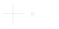
Cursor
|
The cursor can either be cross hairs or a pick box in the Graphics window, depending on the status of the command being carried out. |
|
Command Line
The AGi32 Command Line can be found across the bottom-left corner of the AGi32 interface. The Command Line always displays the status of the current command in progress and prompts for action by the user. Data entry can also be accommodated on the Command Line (right side) when the command in progress is waiting for coordinate entry.
More information about working in AGi32 is available in the AGi32 Overview